
Akash S. Bansode*
Research Scholar, D. K. T. E. Society’s Textile & Engineering Institute, Ichalkaranji.
*All corresponds to email:
Abstract
The ring spinning machine will continue to be the most widely used spinning process in short staple spinning .The spinning geometry is a critical aspect in the spinning process of staple yarn. The spinning geometry influences the distribution of fiber tension in the spinning triangle, twist insertion rate in the yarn, binding-in of fibers, the properties of spun yarns, tension in yarn and the performance of the machine.
The spinning geometry represents the dimensions between the elements of the ring spinning machine which are comes in the path of yarn formation and also the inclinations of elements as well as inclination of the yarn with respect to the parts of the machine. Thus in this paper, different aspects of spinning geometry, influence of the parts of the ring spinning machine on the resultant yarn properties and performance of the ring spinning machine are discussed.
Key words: Ring spinning, spinning geometry, spinning triangle, fiber tension distribution, balloon control ring, balloon height, deflection angle.
- Introduction
The invention of ring spinning machine was done by an American Mr. Thorp in 1828. In that ring spinning machine the modification and implementation of Ring & Traveller elements done by another American Mr. Jenk in 1830. At today’s scenario more than 170 years Ring Spinning has undergone considerable modifications. Evolution of the ring spinning machine is not yet completed.
The ring spinning machine will continue to be the most widely used spinning process in short staple spinning because of it can be used universally, Produces yarn with optimum properties, uncomplicated and easy to control, flexible with regard to volume (blend and batch sizes). In the ring spinning machine the spinning geometry plays an important role regarding quality of yarn and performance of machine.
Definition
Fiber strand passes through the drafting arrangement, thread guide, balloon control ring and traveller. These parts are arranged at various angles and distances relative to one another, which give varying deflections and paths of travel for the yarn. The set of dimensions, guiding and leading angles, of the machine elements with each other on ring frame machine which are together referred as the spinning geometry.
2. Spinning Geometry
Spinning geometry is a geometrical representation of a ring frame machine elements with respect to formation of yarn. Spinning geometry has a significant influence on the spinning operation and the resulting yarn, primarily upon, tension conditions on fibers and yarn, binding-in of the fiber, number of end breaks, yarn hairiness, yarn irregularity and generation of fly etc. Spinning geometry is optimization decisive factor for machinery manufacturers. However, it has to be borne in mind here that changing a spinning geometry parameter inevitably entails a change in all other geometry parameters
It is therefore an absolutely essential set of parameters to be the machine builder. Within the spinning geometry; the following aspects have to be considered.
- The Spinning Triangle
- The Balloon Height
- Roller Overhang
- Drafting arrangement inclination
- Wrap of the yarn on the thread guide
A figure 1 shows a different angle and dimensions in the spinning geometry as follows
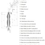
Figure.1- Spinning Geometry
3. Spinning Triangle
The turns of twist in a yarn are generated at the traveller and travel against the direction of yarn movement to the drafting arrangement. Twist must run back as close as possible to the nip line of the rollers, but it never penetrates completely to the nip because, after leaving the rollers, the fibers first have to be diverted inward and wrapped around each other. Accordingly, at the exit from the rollers there is always a triangular bundle of fibers without twist, the so-called spinning triangle. By far the most end breaks originate at this weak point, because the yarn tension in the balloon cannot be transmitted almost without hindrance as far as the drafting arrangement, whereas twist in the spinning triangle is zero-nor does it attain its full value in the adjoining yarn section either, because of friction at the thread guide.
The length of the spinning triangle depends upon the spinning geometry and upon the twist level in the yarn. As can be appreciated from the immediately foregoing remarks, a short triangle represents a small weak point and hence fewer end breaks. As usual, however, advantages have to be weighed against disadvantages.
If the spinning triangle is too short, then the fibers on the edge must be strongly deflected to bind them in. This is not possible with all fibers. Some edge fibers escape the twist effect and are lost as fly. Other may be bound-in, but at one end only; one fiber end them projects from the body of the yarn, which is therefore hairy.On the other hand, a long spinning triangle implies a long weak point and hence more ends breaks. However, a resultant advantage is that the edge fibers are better bound into the edge fibers are better bound into the yarn, which gives a smoother yarn and less fly.
3.1 Spinning Triangle in Compact Ring Spinning:
In the enlarged view of ring spun yarn is examined, it is easy to see that the integration of many fibres is poor, and they therefore make no contribution to yarn strength as shown in Figure 3. In other words, if all fibres could be completely integrated in the yarn, both strength and elongation could in turn be further enhanced. It is thus obvious that even ring-spun yarns are not yet ideal as regards yarn structure.
The development of the compact spinning process began with the desire to achieve a significant improvement in yarn quality by influencing the spinning triangle Figure 3. The process is focused on achieving higher yarn strength and a reduction of yarn hairiness, especially on eliminating the longer hairs, which have a particularly bad influence on the further process. The improvement achieved is shown in the Figure 3.
The Fig. 4(a) displays the fibre triangle at the exit of a conventional ring frame drafting system. The twist imparted by the spindle cannot flow up to the clamping line. The outer fibres spread out and are thus more highly tensioned than those on the inside. The Fig. 4(b) does not show a spinning triangle. The yarn twist flows right up to the clamping line. The yarn is round and smooth. To achieve tenacity comparable with conventional ring-spun yarns, a lower number of turns per meter can be used, which enables higher productivity of the spinning machine, as well as better elasticity and softer hand of different flat textile products.
4. The Inclination of Drafting Arrangement:
The angle of inclination of drafting arrangement (fig. 5) is one factor which determines the height of the spinning triangle. The inclination of drafting arrangement is with respect to the horizontal line of the machine. If the drafting arrangement is mounted with a relatively low inclination, the angle of the wrap of the fiber strand over curvature of the front bottom drafting roller is large; this will give a long spinning angle, with its associated advantages and disadvantages
With a steeper inclination and large angle (α2), the deflection angle £2 is small and the spinning triangle is short. The inclination of the drafting arrangement in modern ring spinning machines now lies between 45° and 60°, very often 45°
5. Roller Overhang:
The top front roller almost never lies vertically above the associated bottom roller known as Roller Overhang (fig. 6). Usually, the top roller is shifted about 2 to 4 mm forward. This gives somewhat smoother running, because the weighting force exerts stabilizing component acting in the running direction so that swinging of the top roller is avoided.Furthermore, the angle of wrap is reduced and the spinning triangle is made shorter. The overhang must not be made too large, however, as otherwise the distance from the exit opening of the roller nip line, becomes too long resulting in poorer fiber guidance and increased yarn irregularity.
Inclination of Stretch Yarn to Vertical:
The yarn run through the thread guide with an inclination giving a deflection angle of about 15º to 30º and a wrap angle (on modern machines of 0º to 50º). This variability arises in part from the up and down movement of the lappets, balloon control rings and ring rail. In addition, there is a very large difference in angle of wrap depending upon whether the yarn in the balloon extends from the guide towards the machine or away from the machine (to the left). The angles therefore never have the same size at any two points around the guide.
The thread guides also exert a braking effect on pulsation of the balloon, which seldom rotates smoothly. It is usually required to absorb impacts and vibration arising from the traveller and from air turbulence. A large deflection damps these impacts and vibrations at the thread guide, so that they no longer penetrate fully to the spinning triangle.
A smaller angle of wrap, therefore, implies more turns of twist in the spinning triangle and fewer end breaks, but also higher yarn tension at that weak point. The latter effect can partly neutralize the favorable effect of the higher twist level. Also, impacts and vibrations are better able to pass through to the spinning triangle. If the twist density is raised at the nip line, them the spinning triangle will also clearly become smaller with all the resulting advantageous and disadvantageous effects.
7. The Balloon Height:
On the ring spinning machine, yarn take up capacity depends on, among other factors, the height of the tube and air turbulence formed by the yarn rotating with traveller speed. However, this height can only be varied within certain a tall balloon implies considerable tension differences between winding of the cop base and winding at the top.
Also, a balloon in this from is unstable; it can collapse. The latter problem can be solved by use of a balloon control ring. However, since the yarn rubs on this ring-and the higher the balloon, the greater the degree of rubbing-use of control rings can lead to roughening of the yarn to a high hairiness value, to increased generation of fly and to melt spots (with synthetic fibers).
8. Other Dimensions in Spinning Geometry
- The lift Ik is about 20 mm shorter than the tube height Ik.
- The distance from the top edge of the tube to the thread guide should be at least 2 dh +5 mm.
- The basic setting of the length Ir (between the ring and the balloon control ring) can be slightly less than half the length IB.
- The ratio (ring diameter)/ (tube height) =0.2-0.225.
- The ratio [tube diameter (top edge)]/[interior ring diameter] = 0.45-0.5
Conclusions:
In Ring Spinning, the Spinning Geometry plays a vital role regarding to the quality of yarn and performance of machine. Spinning geometry has a significant influence on spinning operation and the resulting yarn primarily on: Tension conditions, Binding-in of the fibers, Number of End Breakages, Yarn Hairiness, Yarn Irregularity, and Generation of Fly. Turn the spinning width, should be as close as possible to spinning triangle width to minimize high loss of fiber, minimize hairiness in the yarn. In Compact Ring Spinning system, the width of spinning triangle get reduces the integration of edge fibers in yarn cross section increases. The inclination of the drafting arrangement in modern ring spinning machine now lies between 45° to 60°, very often 45° to get optimum spinning triangle. Roller overhang must not be too large
References:
- Lawrence C. A., “Advances in Spinning Technology”, The Textile Institute, Manchester
- Klein W., “Short Staple Spinning Series Vol. 4” “A Practical Guide to Ring Spinning”
- rikipedia.com
- D. Kane, S.G. Kulkarni , , J. R. Nagla, “Effect of ring frame parameters on blended yarn hairiness and other properties”.
- Carl A. Lawrence, “Fundamentals of Spun Yarn Technology”, CRC Publications, 2003.
- Eric Oxtoby, “Spun Yarn Technology”, Butterworth’s, 1987.
- NCUTE publications on Yarn Manufacturing, Indian Institute of Technology, Delhi.